- 您现在的位置:买卖IC网 > Sheet目录1229 > MCP2515DM-PTPLS (Microchip Technology)BOARD DAUGHTER PICTAIL MCP2515
�� �
�
�MCP2515�
�1.0�
�DEVICE� OVERVIEW�
�1.2�
�Control� Logic�
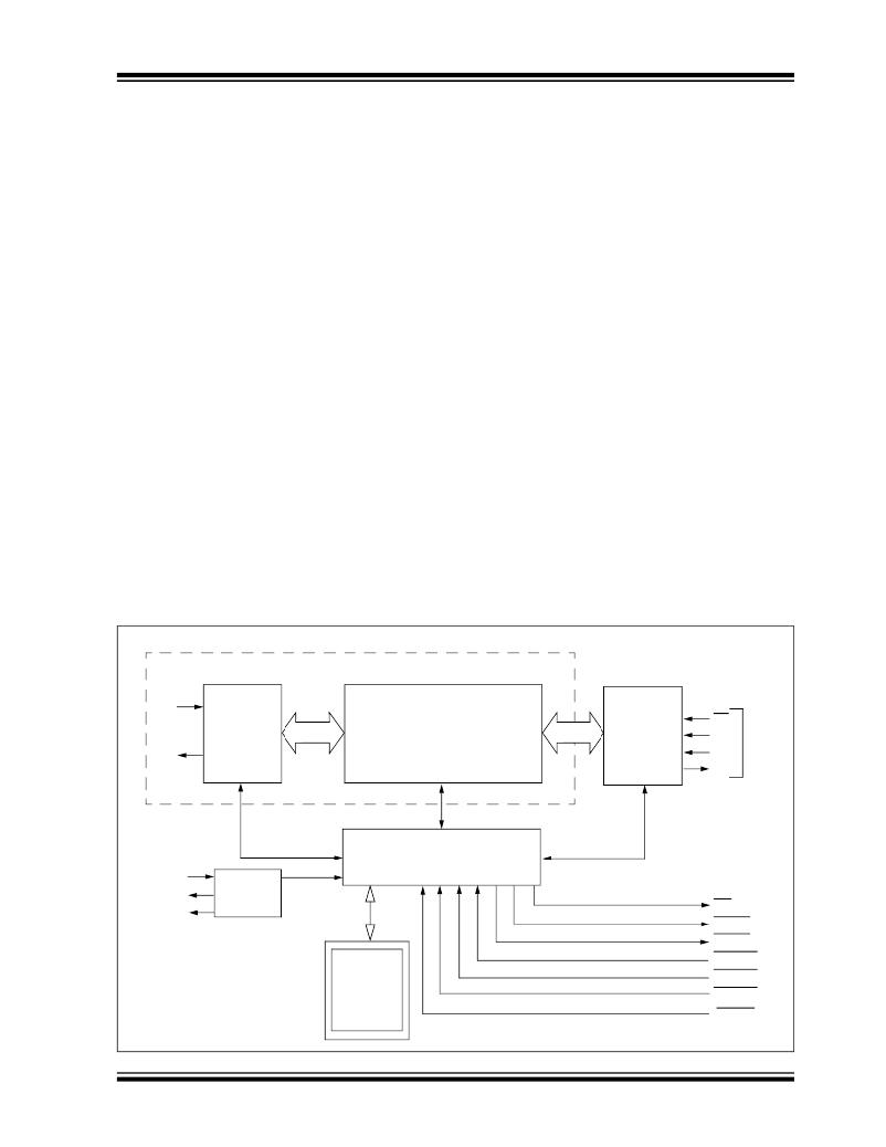
�The� MCP2515� is� a� stand-alone� CAN� controller�
�developed� to� simplify� applications� that� require�
�interfacing� with� a� CAN� bus.� A� simple� block� diagram� of�
�the� MCP2515� is� shown� in� Figure� 1-1� .� The� device�
�consists� of� three� main� blocks:�
�The� control� logic� block� controls� the� setup� and� operation�
�of� the� MCP2515� by� interfacing� to� the� other� blocks� in�
�order� to� pass� information� and� control.�
�Interrupt� pins� are� provided� to� allow� greater� system�
�flexibility.� There� is� one� multi-purpose� interrupt� pin� (as�
�1.�
�2.�
�3.�
�The� CAN� module,� which� includes� the� CAN�
�protocol� engine,� masks,� filters,� transmit� and�
�receive� buffers.�
�The� control� logic� and� registers� that� are� used� to�
�configure� the� device� and� its� operation.�
�The� SPI� protocol� block.�
�well� as� specific� interrupt� pins)� for� each� of� the� receive�
�registers� that� can� be� used� to� indicate� a� valid� message�
�has� been� received� and� loaded� into� one� of� the� receive�
�buffers.� Use� of� the� specific� interrupt� pins� is� optional.�
�The� general� purpose� interrupt� pin,� as� well� as� status�
�registers� (accessed� via� the� SPI� interface),� can� also� be�
�used� to� determine� when� a� valid� message� has� been�
�An� example� system� implementation� using� the� device� is�
��received.�
�Additionally,� there� are� three� pins� available� to� initiate�
�1.1�
�CAN� Module�
�immediate� transmission� of� a� message� that� has� been�
�loaded� into� one� of� the� three� transmit� registers.� Use� of�
�The� CAN� module� handles� all� functions� for� receiving�
�and� transmitting� messages� on� the� CAN� bus.� Messages�
�are� transmitted� by� first� loading� the� appropriate�
�message� buffer� and� control� registers.� Transmission� is�
�these� pins� is� optional,� as� initiating� message�
�transmissions� can� also� be� accomplished� by� utilizing�
�control� registers,� accessed� via� the� SPI� interface.�
�initiated� by� using� control� register� bits� via� the� SPI�
�1.3�
�SPI� Protocol� Block�
�interface� or� by� using� the� transmit� enable� pins.� Status�
�and� errors� can� be� checked� by� reading� the� appropriate�
�registers.� Any� message� detected� on� the� CAN� bus� is�
�checked� for� errors� and� then� matched� against� the� user-�
�defined� filters� to� see� if� it� should� be� moved� into� one� of�
�the� two� receive� buffers.�
�The� MCU� interfaces� to� the� device� via� the� SPI� interface.�
�Writing� to,� and� reading� from,� all� registers� is�
�accomplished� using� standard� SPI� read� and� write�
�commands,� in� addition� to� specialized� SPI� commands.�
�FIGURE� 1-1:�
�CAN� Module�
�RXCAN�
�BLOCK� DIAGRAM�
�CAN�
�Protocol�
�Engine�
�TX� and� RX� Buffers�
�Masks� and� Filters�
�SPI�
�Interface�
�Logic�
�CS�
�SCK�
�SI�
�SPI�
�Bus�
�TXCAN�
�Control� Logic�
�SO�
�OSC1�
�OSC2�
�CLKOUT�
�Timing�
�Generation�
�INT�
�RX0BF�
�RX1BF�
�TX0RTS�
�?� 2003-2012� Microchip� Technology� Inc.�
�Control�
�and�
�Interrupt�
�Registers�
�TX1RTS�
�TX2RTS�
�RESET�
�DS21801G-page� 3�
�发布紧急采购,3分钟左右您将得到回复。
相关PDF资料
MCP3905EV
BOARD DEMO FOR MCP3905
MCP402XEV
BOARD EVAL FOR MCP402X
MCP42XXEV
BOARD EVALUATION MCP42XX
MCP43XXEV
BOARD EVALUATION MCP43XX
MCP46XXDM-PTPLS
BOARD PICTAIL DIGI POT MCP4XXX
MCP46XXEV
EVAL BOARD FOR MCP46XX
MCP4XXXDM-DB
BOARD DAUGHTER DIGIPOT MCP4XXX
MCP6S2XEV
BOARD EVALUATION FOR MCP6S2X
相关代理商/技术参数
MCP2515-E
制造商:MICROCHIP 制造商全称:Microchip Technology 功能描述:Stand-Alone CAN Controller with SPI Interface
MCP2515-E/ML
制造商:Microchip Technology Inc 功能描述:
MCP2515-E/P
功能描述:网络控制器与处理器 IC W/ SPI Inter 125dC RoHS:否 制造商:Micrel 产品:Controller Area Network (CAN) 收发器数量: 数据速率: 电源电流(最大值):595 mA 最大工作温度:+ 85 C 安装风格:SMD/SMT 封装 / 箱体:PBGA-400 封装:Tray
MCP2515-E/SO
功能描述:网络控制器与处理器 IC W/ SPI Inter 125dC RoHS:否 制造商:Micrel 产品:Controller Area Network (CAN) 收发器数量: 数据速率: 电源电流(最大值):595 mA 最大工作温度:+ 85 C 安装风格:SMD/SMT 封装 / 箱体:PBGA-400 封装:Tray
MCP2515-E/SORB4
制造商:Microchip Technology Inc 功能描述:
MCP2515-E/ST
功能描述:网络控制器与处理器 IC W/ SPI Inter 125dC RoHS:否 制造商:Micrel 产品:Controller Area Network (CAN) 收发器数量: 数据速率: 电源电流(最大值):595 mA 最大工作温度:+ 85 C 安装风格:SMD/SMT 封装 / 箱体:PBGA-400 封装:Tray
MCP2515-I
制造商:MICROCHIP 制造商全称:Microchip Technology 功能描述:Stand-Alone CAN Controller with SPI Interface
MCP2515-I/ML
制造商:MICROCHIP 制造商全称:Microchip Technology 功能描述:Stand-Alone CAN Controller with SPI Interface